Enerpro Locomotive Power Electronics Converter (ELPEC)
The ELPEC is a solid state rectifier that outputs 425 amps of power for locomotive 74V DC loads. It provides a reliable and proven option for eliminating the auxiliary generator on locomotive repower projects. The ELPEC is powered by either isolated windings from the Companion Alternator (CA) or from the main CA stator windings through an isolation transformer. The complete system includes the ELPEC, a diode shunt module, and an inductor-capacitor filter to provide low ripple output power. A clean and flexible locomotive computer interface simplifies system integration.
A key feature of the ELPEC is patented 3-stage battery charging, which has many advantages over constant voltage charging including longer battery life, greatly reduced sulfation, and shorter time to charge. Contact an Enerpro engineering representative to discuss installation options.
Key Features:
- 3-stage Charging
- Simple and adaptable locomotive interface
- Proven robust design
- Thermal self-protection
Technical Details
Three-Stage Charge Profile
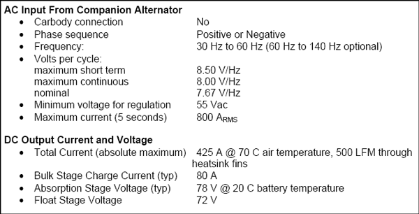
Air pollution regulations and high fuel costs have made locomotive operators shut down idling locomotives much more frequently than in the past. This change in locomotive operation has resulted in premature loss of battery capacity and more frequent cell failure rate. These problems are caused by the single-stage charge profile provided by conventional chargers, whether implemented by an Auxiliary Generator-powered diode rectifier or a Companion Alternator-powered SCR rectifier. With single-stage charging, the initial current immediately after engine start is limited only by generator output and battery circuit resistance. Most locomotive battery charging circuits incorporate a current limiting resistor to reduce the charge current. Even with this resistor, the initial current can greatly exceed the battery manufacturer’s recommended maximum charging current and shorten battery life. The single-stage charger transitions from the high initial first-stage current when the battery voltage rises to reach the nominal voltage setpoint of 74 V. The single-stage charger then maintains constant nominal 74 V on the battery until the engine is shut down. According to battery experts, 74 V is insufficient to convert all of the battery’s active material during the engine run time if the engine is shut down several times per day. The result is a progressive loss of capacity.
The three-stage charge profile produced by the ELPEC regulates the first, or Bulk Stage, current to the manufacturer’s typically recommended 20% of capacity. In the second, or Absorption Stage, the rectifier voltage is regulated to typically 78 V. This elevated voltage converts the maximum amount of active battery material while equalizing the charge in each cell, thus minimizing sulfation and capacity loss. In the third, or Float Stage, the ELPEC reverts to a constant-voltage regulation mode (nominally 72 V).
Bulk Stage
After engine start, the unit enters the 80 A constant-current Bulk Stage. The battery behaves as a capacitor in that the constant charging current results in battery voltage increasing linearly with time. The Bulk Stage ends when the voltage reaches a converter-imposed limit of typically 78 V (2.44 Volts per cell).
Absorption Stage
The constant voltage Absorption Stage begins with the battery charged to about 80% total capacity. The Absorption Stage current decays exponentially with time from the initial 80 A until it reaches one of two Float Stage thresholds. The transition to the Float Stage occurs when one of two conditions are met:
- The Absorption Stage current decays to typically 25 A, or
- The total Absorption Stage charge reaches approximately 25% capacity.
Forcing the Absorption/Float transition to occur as a function of charge assures that a shorted cell or other battery defect will not result in continuous operation at elevated voltage.
Float Stage
During the regulated 72V Float Stage, the battery current gradually decays to the steady-state self-discharge current. This maintains a full battery charge as long as the engine is running.
Block Diagram
The ELPEC is configured in a locomotive system as shown in Enerpro drawing E1735. The conversion is achieved by means of a six-thyristor rectifier bridge that is connected to an isolated winding on the companion alternator. If an isolated Companion Alternator winding is not available, the ELPEC may be powered through an appropriate isolation transformer. Thyristor firing, voltage regulation, current regulation, and control interfacing is achieved by a charge control and thyristor firing board as shown. The DC output is filtered with a typical series inductor/shunt capacitor arrangement and fed to a diode/shunt assembly. The battery current shunt feedback signal is isolated from the firing/regulator board by means of a precision isolation amplifier. Critical and non-critical loads may be split as needed by using the appropriate terminal lug on the diode/shunt assembly.
ENVIRONMENTAL SPECIFICATIONS
The ELPEC is an open-frame assembly. Environmental specifications that are enclosuredependent, such as salt fog and dust infiltration, are deferred to the customer-supplied enclosure requirements. Any responsibility for environmental qualification rests with the customer.
Cooling Air Temperature
- -40° C to 65° C continuous at rated current
- 100° C for 15 minutes at reduced current (tunnel operation)
- -40° C to 65° C storage
The ELPEC incorporates a temperature sensor circuit that linearly reduces the available output current from the rated maximum current to zero current when the thyristor temperature exceeds a preset limit. This circuit ensures that the current capacity of the ELPEC is fully utilized while keeping the thyristor junction temperature below a safe level.
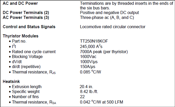
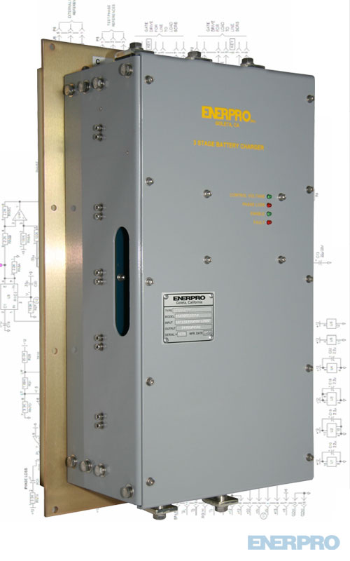
The Enerpro-designed and manufactured combination regulator, gate trigger, and controller circuit board and snubber board, along with the thyristor modules, bus bars/terminals, current shunt and thyristor temperature sensor are mounted on a finned-on-one-side aluminum extrusion and adaptor plate. These components form an open frame assembly with envelope dimensions of 22.75 in. (578 mm) length x 11.44 in. (291 mm) width x 8.65 in. (220 mm) depth. The assembly is attached to a panel with the heat sink fins protruding into the air stream behind the panel as seen in Drawing M1888.
Altitude
-100 to +11000 feet above sea level.
Shock and Vibration
The ELPEC is designed to withstand continuous high shock and vibration in both directions of all three planes at an as-yet to be determined frequency.
Maintenance
Occasional cleaning of the heat sink fins may be required to maintain full rated current capability. Clean, dry cooling air should be used
Electro-Magnetic Compatibility
Compatibility with the following EMI tests has been tested in similar projects with excellent results. Note that the customer assumes responsibility for EMI certification testing.
- Conducted Susceptibility
- Radiated Susceptibility
- Conducted Emissions
- Electrostatic Discharge
Failure Rate
The useful design life is 16 years in freight locomotive service with a critical failure rate of less
than 2% per year. The ELPEC is unit-serviceable in event of failure.
Efficiency
The ELPEC efficiency is greater than 95% from 20% to 100% of rated load.
Load Filter
An LC filter reduces the ripple current voltage applied to the battery and other loads. The filter resonant frequency selected should be less than six times the lowest generator frequency. The filter attenuation should limit the ripple voltage to less than 5% of the dc voltage. The Enerpro Capacitor Filter Assembly (CFA-1) provides 0.1 F (200 Vdc working, 250 Vdc surge) of capacitance in a compact, ruggedized package suitable for rail applications.
Control (Enable Command) Power
All control and enable command power is derived directly from the locomotive battery.
Firing/Regulator Board
The FCROVF6-TSCS-1 variable frequency firing/regulator board uses the field-proven elements of the rail industry-standard FCOVF6100 variable frequency firing board and the VLTLCL-1 regulator board, originally developed for a mining truck battery charger application. This board also includes custom fault monitoring, control interface, and battery current regulation features not present in other Enerpro products. The printed circuit board is a sixlayer, 0.093”-thick FR-4 epoxy laminate with plated through holes and solder mask over bare copper. All bare Enerpro circuit boards conform to UL94-V0. A polyurethane conformal coating (MIL-1-46056, Type UR) is applied to the printed circuit board to provide enhanced immunity to dirt and moisture.
Snubber Board
In a thyristor converter, a high rate-of-rise in anode to cathode voltage, or dV/dt, occurs when a thyristor ceases conduction or when another thyristor in the circuit is gated into conduction. The dV/dt of the thyristor voltage must be limited to avoid erratic circuit operation and device damage. Connected anode to cathode, the snubber circuit resistors and capacitors limit this dV/dt. Specifically designed for use in high vibration environments, the TSBHG-6 board uses rail mounted TO-220 style resistors and high-quality, board mounted WIMA film capacitors. This configuration minimizes the susceptibility of the solder joints to vibration and provides a convenient heat sinking scheme for the snubber resistors.
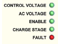
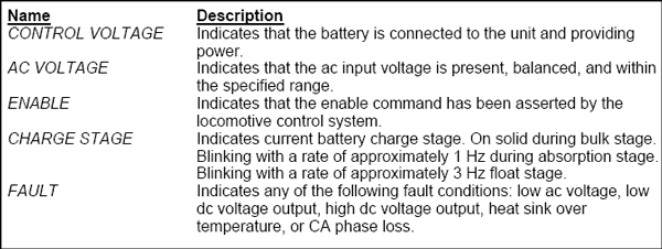
Status LED Indicators
System Connections and Setup
System Connections and Setup
Refer to connection diagram E1735. All internal connections are completed at the factory. Connections for ac and dc power are made directly to the bus bars, which are fitted with captive 1/2-13 UNC threaded PEM nuts. Enable and status read-back signals are available on connector J1, which is a weather-tight, keyed, bayonet-style cylindrical connector (MIL 5015 series, 24-5 insert).
APPLICABLE DOCUMENTS
- E1735, Connection Diagram, “ELPEC 74 V Controlled Rectifier & Battery Charger”
- E1734, Schematic Diagram, “FCROVF6-TSCS-1, Simplified Variable Frequency Firing Circuit with Three-Stage Charging”
- E459, Schematic Diagram, “High Shock 6-Circuit Snubber Board, TSBHG-6”
- M1888, Mechanical Diagram, “ELPEC Phase Controller”
REFERENCE DRAWING E1735
PRELIMINARY– REFERENCE DRAWING E1735